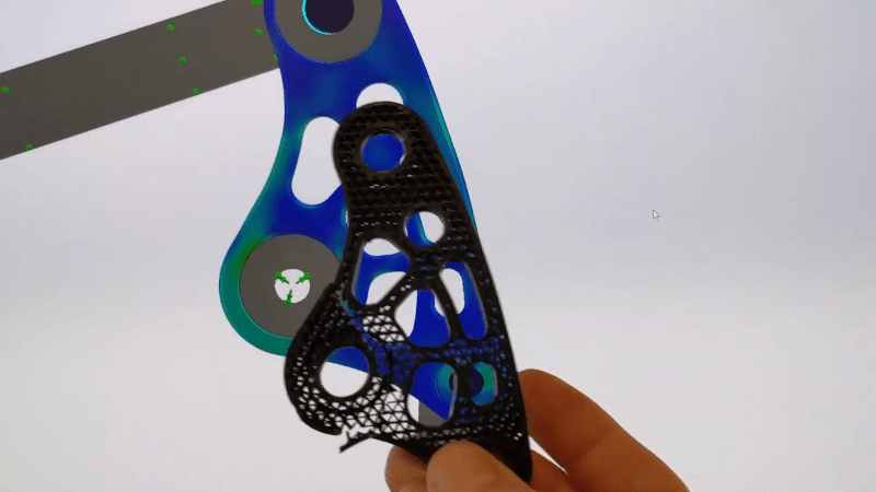
Finite Element Analysis vs Real World

In advanced engineering circles, the finite element method — or, more commonly, finite element analysis — is a real staple. With the advent of more powerful home computers, though, even your home projects can benefit. The technique itself is very general, but you usually see it used for structural analysis. However, you might wonder how well it corresponds to reality. That is if analysis shows a segment of your part is weak (or strong) does that hold true when you actually build the part? [Fiveohno] wondered the same thing and decided to do some testing, which you can see in the video below.
Of course, like any simulation, the accuracy will only be as good as your data input and model. But if you work carefully, it should match up pretty well to the real world, so it is interesting to see the results of a real-world test. In fact, a video from Solidworks that shows a similar part points out — inadvertently — what not to do. For example, the force used in that analysis was too low and at a point where the part was at relatively low stress instead of at the maximum stress.
In general, the finite element method deals with solving differential equations. It is a complicated topic, but in a nutshell, you break up a part into many small pieces (a mesh) and then work with simple equations that represent just that small piece. In the case of the experiment, the model was for a suspension rocker link for a bike that receives a lot of stress.
The actual experiment is nearly 11 minutes in. Enough stress causes the part to break. Then looking at the analysis, you can see the physical damage matches pretty closes to the simulation results.
We love seeing real life compared to virtual simulations. If you want to learn more about finite-element analysis and you weren’t at our Remoticon, you can catch the replay. If you want to apply the technique to your infill patterns, we’ve seen it done.
Post a Comment