How To Modify Your Car Stereo for Bluetooth or Aux-In
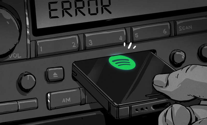
If you’re an automotive enthusiast of taste, you can’t stand the idea of fitting a janky aftermarket stereo into your nice, clean ride. Flashy, modern head units can spoil the look of a car’s interior, particularly if the car is a retro, classic, or vintage ride.
Thus, we’re going to look at how to modify your existing stock car stereo to accept an auxiliary cable input or even a Bluetooth module. This way, you can pump in the latest tunes from your smartphone without a fuss, while still maintaining an all-original look on the dash.
Fundamentals
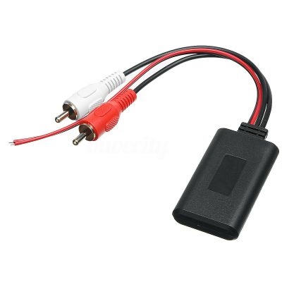
Depending on your choice of audio player, you may prefer a 3.5 mm aux jack, or you might want to go with Bluetooth audio if your smartphone no longer has a headphone port. Whichever way you go, the process of modifying the stereo is largely the same. To achieve your goal, you need to find a way of injecting the audio signal into the head unit’s amplifier stage, while making sure no other audio sources are getting sent there as well.
Whether that audio source is a 3.5 mm jack or a Bluetooth module doesn’t matter. The only difference is, in the latter case, you’ll want to buy a Bluetooth module and hardwire it in to the auxiliary input you create, while also splicing the module into the stereo’s power supply. In the case of a simple headphone jack input, you simply need to wire up an aux cord or 3.5 mm jack somewhere you can get to it, and call it done.
This guide won’t cover every stereo under the sun, of course. Edge cases exist and depending on the minute specifics of how your original car radio works, these exact methods may or may not work for you. However, this guide is intended to get you thinking conceptually about how such mods are done, so that you can investigate the hardware in front of you and make your own decisions about how to integrate an external audio input that suits your usage case.
Guide 1: Old School Radio/Cassette Decks
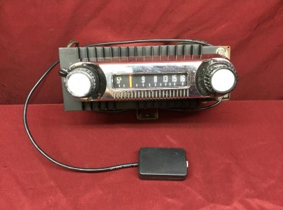
If you’ve got something quite retro, this hack can be very simple indeed. This normally applies to radio/cassette players from the 1970s and early 1980s that have an analog volume knob on the front. In this case, the audio signal flows to the amplifier directly through the volume knob. Some kind of rudimentary switching decides whether the radio or cassette signals get to the volume knob and are then passed out to the amplifier section and on to the speakers.
Thus, there are a number of ways you can splice in your own audio on these units. The easiest is to cut the stereo audio traces or wires going to the volume knob, and hook them up to a DPDT toggle switch. Hook the volume knob’s wires up to the middle two pins of the switch, and hook the original stereo feed up to a pair of pins on one side. You can then wire in your new aux cord or Bluetooth input up to the other pins on the toggle switch. The toggle switch then selects between standard operation, or the external feed. Install that switch somewhere tidy and the job is done!
Alternatively, you might find that there’s a button on the deck that switches the radio into cassette mode whether or not a tape is inserted. In that case, you may be able to wire up your auxiliary audio into the cassette module’s audio output, and simply use the existing switches on the deck to select cassette mode. With no cassette in the deck providing a signal, only your external audio will be going through to the volume knob and then on to the speakers. Easier, and even cleaner!
Guide 2: Digital Era Radio/Cassettes and CD Players
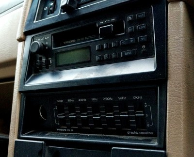
Head units from this era are usually easy to hack, with relatively large components and traces inside and simple signal flows. The equalizer input could likely also easily be modified in a similar way to the Guide 1 method.
In the digital era, things get a touch more complicated. This refers to head units that use digital displays and push button controls, with a microcontroller running the whole show. Interestingly, many 1980s and 1990s radios used simple 4-bit microcontrollers, which had just enough capability to run a simple head unit while being presumably cheaper than the more usual 8-bit parts. Basically, if your 80s or 90s stereo has an LCD on it, this part of the guide may be for you.
Digitally-controlled decks typically use a chip called a mux or a multiplexer to determine which signal gets sent to the amplifier. The mux is basically a chip with many inputs and a single output. The main microcontroller in the head unit will typically control the mux chip, either by toggling a few GPIO pins or using a serial, SPI, I2C, or other interface. When a user presses the button for the FM radio, for example, the microcontroller will send a signal to tell the mux to route the FM radio input to the output to the amplifier. If they hit the button for tape, the microcontroller will instruct the mux to route out the tape audio instead.
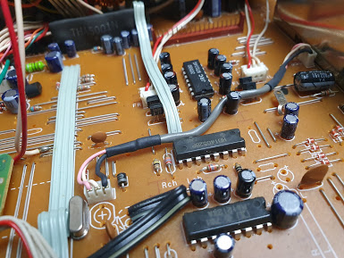
Thus, by controlling the mux, you can control the audio that gets to the amplifier and thus the speakers. Depending on the mux chip used, and how integrated it is with the rest of the hardware in the stereo, this can be easy or rather difficult.
Most muxes will be a variant of the 4051/4052 series. For example, an early 90s stereo using the Hitachi HD14052BP multiplexer is easily modified with an auxiliary input; simply flipping a few pins changes the mux’s input. Thus, with a properly wired switch, the mux can be told to select the cassette or CD input even when no cassette or CD is present. Simply then wire up your aux input to those same pins and you’re in business.
Guide 3: Modern-Era CD Decks
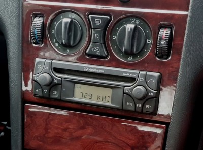
It uses an integrated mux and signal processor, making it harder to hack an audio input into the stereo. The newer technology also uses finer-pitch surface mount parts, making it harder to work with for beginners.
More modern stereos can prove difficult, however. Often, the multiplexer is integrated into more complicated chips that handle multiple functions. To get the multiplexer to switch inputs, it often requires the use of a silent audio CD, or commanding these chips over interfaces like I2C, serial, or SPI. This is on top of the job of wiring in the auxiliary input into the tape, CD, or other audio input subsystem.
For instance, the Mercedes Audio 10 CD head unit, as produced by Alpine in the late 1990s, features the Philips TEA688OH signal processor IC. This chip handles volume, treble, and bass controls, as well as certain radio signal processing tasks while also acting as the multiplexer as well.
Wiring the auxiliary input into the CD input is simple enough, but getting the stereo to actually switch to that input is harder. Many elect to simply burn an audio CD with a silent track that lasts an hour. Inserting that into the deck gets the CD input selected, and the auxiliary audio can play through on top of the silent output from the CD itself. However, it’s an inelegant solution that requires the user to keep a disc on hand to switch into auxiliary mode, and it also means the mechanical disc player must be maintained in working order.
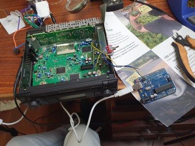
A more elegant solution in this case would be to force the TEA688OH to switch to the CD input, or another input, regardless of whether or not a CD was in the drive. This is quite possible, as the chip receives signals from the main microcontroller over I2C, and these are all listed in the chip’s datasheet. However, it requires adding in a Arduino or similar that can speak I2C, a DPDT relay, and some supporting components.
The I2C lines between the stereo’s microcontroller and the TEA688OH signal processor must be cut, and wired up to the relay. Under command from the Arduino, the relay normally routes signals from the stock microcontroller to the signal processor, allowing the normal control of volume and other features.
However, if the user wishes to switch to their aux input wired into the CD input, they can simply press a button hooked up to the Arduino. The Arduino then flips the DPDT relay, connecting its own I2C interface to the signal processor. Then, the command to switch inputs can be sent over I2C, and then control restored to the standard microcontroller so normal functionality of volume controls and such is resumed.
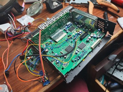
Obviously, the latter case is much harder work, and requires knowledge around the use of microcontrollers and I2C communications. The final result is a lot more elegant, however, with the unit able to switch over to auxiliary input at the touch of a button. While the example given is for a specific Mercedes head unit, other OEM stereos from the era use similar components, and can be modified in a similar way. It’s simply a matter of finding a way to get your auxiliary input piped out to the amplifier subsection via the onboard multiplexer.
Appendix: CD Changer Inputs
Sometimes, you get lucky, and there’s a simple additional input already hanging off the back of your standard stereo. Often, stock stereos come with a CD changer input so that the option can easily be added to cars without changing over the basic head unit. These inputs typically come with analog audio inputs and even a power supply, with a rudimentary way of determining whether a CD changer is connected. In the case of the Kenwood standard CD changer input, it’s as simple as tying a certain pin to another via a resistor, and the head unit can be switched to the CD changer input and audio can be piped in.
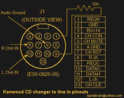
However, others are more complex. Certain luxury cars in the late 1990s use a digital audio input over optic fibre that is difficult to spoof with off-the-shelf hardware. Also, some head units use serial or other communication methods to control the CD changer and won’t switch to the input unless they receive the right messages back from the hardware. If you don’t have a CD changer already, it can be difficult to figure out how to spoof this communication as well.
It’s a great method if you can make it work, though. Often it allows a custom input to be hacked in without even opening the stereo. Old-school car audio hackers have been doing it for decades in cars like the Mazda Miata, swapping in their own audio inputs without spoiling the tasteful stock look of the original dash layout.
Summary
Overall, all you need to do to hack in an auxiliary audio input, whether Bluetooth or otherwise, is to get your signal to the amplifier in the place of any other. If you can figure out how signals are routed from the various subcomponents of the head unit – such as the CD player, tape deck, and radio modules – then you should be able to figure out how to route in your own signals instead. Hopefully this guide has served to illustrate the basic processes required so that you can figure out how to hack any stereo out there. Good luck, and if you pull off a particularly nice hack, send it in on the tip line. Have fun!
Post a Comment