Identify That Antenna By Sight

It’s a skill that radio amateurs pick up over years but which it sometimes comes as a surprise to find that is not shared by everyone, the ability to casually glance at an antenna on a mast or a rooftop and guess what it might be used for. By which of course I mean not some intuitive ability to mentally decode radio signals from thin air, but most of us can look at a given antenna and immediately glean a lot of information about its frequency and performance. Is this privileged knowledge handed down from the Elmers at the secret ceremony of conferring a radio amateur’s licence upon a baby ham? Not at all, in fact stick around, and I’ll share some of the tricks.
It’s The Size That Matters.
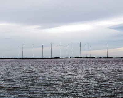
We normally think of frequencies in megahertz, or sometimes in kilohertz or gigahertz. But the other side of the frequency coin is wavelength in metres, the length of one cycle as it travels in free space. A function of radio waves traveling at the speed of light is that the frequency corresponds to the number of cycles that can be fitted into the distance light travels in a second. Thus if we take the speed of light to be the taught-to-schoolkids 3 x 10^8 metres per second then, that means that the wavelength is 3 x10^8 divided by the frequency in hertz. a more practical version of the formula is that 300 divided by the frequency in megahertz returns the wavelength in metres, so for example the wavelength at 100 MHz is 3 metres. The lower the frequency the longer the wavelength, thus lower frequency antennas are larger than higher frequency ones.
Knowing the wavelength of a particular frequency immediately gives us a handle on the size of antenna required to use it, but it’s not quite as simple as a 3 metre antenna being designed for 100 MHz. Instead the archetypal antenna uses a fraction of the wavelength, usually a half or a quarter, so immediately an element of identifying the type of antenna comes into play. You’ll need to hone your skills in guessing dimensions at a difference, for this it’s useful that there is often a mast or other easily gauged structure for a reference.
Just What Am I Looking At
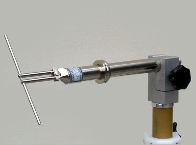
The most basic of antenna designs will be familiar to many readers as the dipole, two conductors each a quarter wavelength long arranged in a straight line with a usually coaxial feeder connected between them in the centre. It’s the antenna from which many other designs are derived, so knowing how to spot it within those other antenna designs gives you an immediate handle on how long a quarter or a half wavelendth is at that frequency. A 100 MHz antenna is therefore half of the 3 metre wavelength, or around 1.5 metres long. If you cast your eye around the rooftops until you see someone with an FM radio dipole antenna for 88 to 108 MHz then, it will be somewhere about that size.
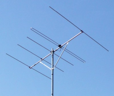
If you cast your eye around the antennas on rooftops, on utility buildings, and in other places, you’ll notice that few of them are dipoles. Many of them are long spiky affairs, a central boom with a ling of elements at right angles to it, or a triangular shaped array of elements yet again along a central boom. A rooftop TV antenna is a great example of the type, called a Yagi-Uda array after its inventors. They set out to create a wireless energy transmission system using radio waves, and found themselves instead creating a highly directional array in which a dipole was joined by a set of passive elements. The dipole is still the same though, so if you can estimate its size you can home in on the frequency.
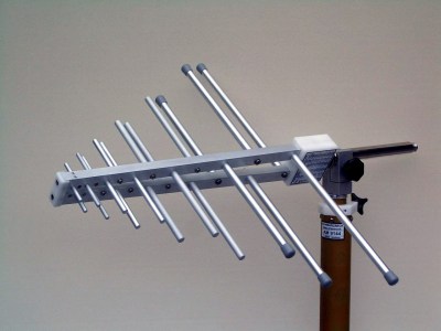
There’s another type of antenna similar to the Yagi-Uda array, which looks extremely similar except for a characteristic triangular shape. This is a wideband antenna called a log-periodic, and it’s an array of dipoles of different frequencies. Yet again if you can estimate the size of each dipole it’s possible to work out the spread of frequencies by looking at the largest and smallest ones.
Both a Yagi-Uda and a log-periodic antenna are directional, so besides working out its frequency you can also tell where the station it’s communicating with is. I once spent a mildly enjoyable summer afternoon on a motorcycle combing the lanes of Oxfordshire to find the base station for the local village water plants this way, as each of them had a Yagi at about 450 MHz on a small mast By lining them all up on the map I was able to find the control point, not particularly surprisingly it was at the sewage plant in my local small town.
There’s a final type of antenna that you’ll see a lot of on vehicles and in other places, the vertical or whip antenna. The simplest of these is a quarter-wavelength springy wire making it easy to guess the frequency, but there are several complications which can put a guess off-course. You’ll often see whip antennas with coils either at the bottom or some point half way up, these can be loading or phasing coils to change the antenna’s performance. Usually they are to help pack a larger antenna into a smaller space, which makes the overall length less useful as a guide. If there’s a secret, it’s that most amateurs have seen enough antennas by now that we recognise the difficult ones by comparison to those we’ve seen. Apologies, maybe you do need an Elmer to pass this down after all.
Header: Bert Kaufmann from Roermond, Netherlands, CC BY 2.0.
Post a Comment