This Custom Dynanometer Is A Sterling Example of Homebrewing

[Leo Fernekes] has fallen down the Sterling engine rabbit hole. We mustn’t judge — things like this happen in the best of families, after all. And when they do happen to someone like [Leo], things can get interesting mighty quickly.
His current video, linked below, actually has precious little to do with his newfound Sterling engine habit per se. But when you build a Sterling engine, and you’re of a quantitative bent, having some way to measure its power output would be handy. That’s a job for a dynamometer, which [Leo] sets out to build in grand fashion. Dynos need to measure the torque and rotational speed of an engine while varying the load on it, and this one does it with style.
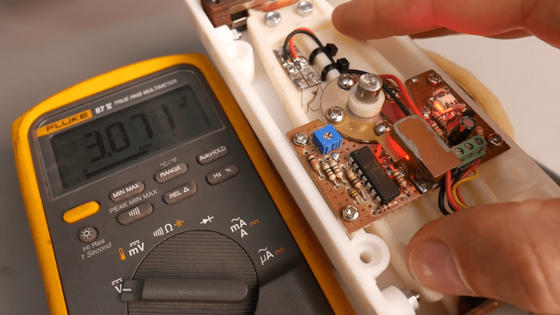
[Leo]’s torque transducer is completely DIY, consisting of hand-wound coils on the ends of a long lever arm that’s attached to the output shaft of the engine under test by a magnetic coupling. The coils are free to move within a strong magnetic field, with a PID loop controlling the current in the coils. Feedback on the arm’s position is provided by an optical sensor, also DIY, making the current necessary to keep the arm stationary proportional to the input torque. The video goes into great detail and has a lot of design and build tips.
We just love the whole vibe of this build. There may have been simpler or quicker ways to go about it, but [Leo] got this done with what he had on hand for a fraction of what buying in off-the-shelf parts would have cost. And the whole thing was a great learning experience, both for him and for us. It sort of reminds us of a dyno that [Jeremy Fielding] built a while back, albeit on a much different scale.
Post a Comment