
The $50 Ham: A Simple WSPR Beacon

I was having a chat recently with someone, and it surprised me that she had an amateur radio license. I suppose it shouldn’t have come as much of a surprise; after all, getting a ham radio license is a pretty common rite of passage in the life of a hardware hacker. I guess it surprised me because she’d never mentioned it in our past conversations, and as we talked about it, I learned why. “I got my license because I thought ham radio was about building radios, ” she said. “But it’s not.”
In a lot of ways, she is right about the state of ham radio. There was a time that building one’s own gear was as central to the hobby as getting on the air, and perhaps more so. Now, though, with radios as cheap as $30 and the whiz-bang gear that can make reaching out across the planet trivially easy, building your own radios has slipped down a few notches. But homebrewing is far from a dead art, and as we’ll see in this installment of “The $50 Ham”, a WSPR beacon for the HF bands is actually a fun and simple — and cheap — way for the homebrew-curious to get a taste of what it’s like to build your own transmitter.
A Minimalist Approach
In the last $50 Ham installment, I talked about how the Weak Signal Propagation Mode, or WSPR, is used to explore propagation conditions across the world. The concept is simple: a transceiver connected to a WSPR client program, such as the one built into WSJT-X, listens for the FSK-modulated signals that are being transmitted by other stations. The low-bit-rate signals encode a minimal message — the transmitting station’s callsign, Maidenhead grid location, and the transmit power — into a digital signal that takes nearly two full minutes to send. The receiving station then reports the decoded message to a central WSPR database, which keeps track of the contacts and can display a map of paths between stations.
On the receiving end, most of the magic of WSPR lies in the software, particularly in the digital signal processing that pulls data from the oftentimes weak and degraded signal. But the transmitting side is another story; there, the software needed to encode the minimal message is pretty simple, so simple that not much more than a microcontroller is needed to do the job. Really, all that’s needed is an oscillator capable of generating a signal at a fixed frequency, and varying that frequency under software control to encode the message.
There are a lot of ways to go about this, including using the GPIO pins on a Raspberry Pi to generate the RF signal directly. In this case, though, I decided to follow the lead of a lot of other hams and use an Si5351 clock generator breakout board and an Arduino Nano. The clock generator board sports a three-channel PLL-controlled oscillator that talks I2C and has a well-supported library, making it easy to implement a simple oscillator for just about any band.
I decided to make my WSPR beacon for the 20-meter band, for no real reason other than I’ve always had good luck making WSPR contacts on that band during the daylight hours, which is when I spend the most time in my shack. I also decided that for at least my first pass at this project, I’d strip out all the bells and whistles that are so easy to add to an Arduino project. WSPR transmissions need to be carefully synchronized to start at the top of every even-numbered minute, so many of these projects include elaborations such as a GPS receiver or an NTP client to take care of timing. I figured it would be a lot quicker and easier for me to simply watch the clock and press a button to start the WSPR transmission cycle at the proper time.
To that end, I searched for “minimal WSPR transmitters” and found a number of designs that would work for me, including this one by Peter B. Marks. He adapted the code from Jason Milldrum’s (NT7S) examples in his excellent Etherkit library for the Si5351 — we all borrow from each other. My only addition to the code is support for a button to kick off the transmitter. The code simply takes my callsign, grid square, and transmit power, encodes it into a WSPR message, and tells the Si5351 to send the sequence of four different FSK tones that make up the 162-symbol-long message.
/*
* Minimal WSPR beacon using Si5351Arduino library
*
* Based on code:
* Copyright (C) 2015 - 2016 Jason Milldrum
*
*
* This program is free software: you can redistribute it and/or modify
* it under the terms of the GNU General Public License as published by
* the Free Software Foundation, either version 3 of the License, or
* (at your option) any later version.
*
* This program is distributed in the hope that it will be useful,
* but WITHOUT ANY WARRANTY; without even the implied warranty of
* MERCHANTABILITY or FITNESS FOR A PARTICULAR PURPOSE. See the
* GNU General Public License for more details.
*
* You should have received a copy of the GNU General Public License
* along with this program. If not, see
* https://gist.github.com/NT7S/2b5555aa28622c1b3fcbc4d7c74ad926.
*/
#include "Arduino.h"
#include "si5351.h"
#include "Wire.h"
#define TONE_SPACING 146          // ~1.46 Hz
#define WSPR_CTC 10672            // CTC value for WSPR
#define SYMBOL_COUNT WSPR_SYMBOL_COUNT
#define CORRECTION 94674          // Determined experimentally -- parts per billion?
#define INPUT_PIN 7               // pushbutton
#define TX_LED_PIN 13

Si5351 si5351;
JTEncode jtencode;

unsigned long freq = 14097100UL;  // Transmit frequency
char call[7] = "N7DPM";           // Callsign
char loc[5] = "DN17";             // Grid square
uint8_t dbm = 10;                 // Transmit power
uint8_t tx_buffer[SYMBOL_COUNT];
int val = 0;

// Global variables used in ISRs
volatile bool proceed = false;

// Timer interrupt vector. This toggles the variable we use to gate
// each column of output to ensure accurate timing. Called whenever
// Timer1 hits the count set below in setup().
ISR(TIMER1_COMPA_vect)
{
    proceed = true;
    // Serial.println("timer fired");
}

// Loop through the string, transmitting one character at a time.
void encode()
{
    uint8_t i;
    Serial.println("encode()");
    jtencode.wspr_encode(call, loc, dbm, tx_buffer);

    // Reset the tone to 0 and turn on the output
    si5351.set_clock_pwr(SI5351_CLK0, 1);
    digitalWrite(TX_LED_PIN, HIGH);

    // Now do the rest of the message
    for (i = 0; i < SYMBOL_COUNT; i++)
    {
        uint64_t frequency = (freq * 100) + (tx_buffer[i] * TONE_SPACING);
        si5351.set_freq(frequency, SI5351_CLK0);
        Serial.print("freq = ");
        Serial.println(tx_buffer[i]);
        proceed = false;
        while (!proceed);
    }
    Serial.println("message done");
    // Turn off the output
    si5351.set_clock_pwr(SI5351_CLK0, 0);
    digitalWrite(TX_LED_PIN, LOW);
}

void setup()
{
    Serial.begin(115200);
    Serial.println("setup");

    // Use the Arduino's on-board LED as a keying indicator.
    pinMode(TX_LED_PIN, OUTPUT);
    digitalWrite(TX_LED_PIN, LOW);

    // Initialize the Si5351
    // Change the 2nd parameter in init if using a ref osc other
    // than 25 MHz
    si5351.init(SI5351_CRYSTAL_LOAD_8PF, 0, CORRECTION);

    // Set CLK0 output
    si5351.set_freq(freq * 100, SI5351_CLK0);
    si5351.drive_strength(SI5351_CLK0, SI5351_DRIVE_8MA); // Set for max power
    si5351.set_clock_pwr(SI5351_CLK0, 0);                 // Disable the clock initially

    // Set up Timer1 for interrupts every symbol period.
    noInterrupts(); // Turn off interrupts.
    TCCR1A = 0;     // Set entire TCCR1A register to 0; disconnects
    // interrupt output pins, sets normal waveform
    // mode. We're just using Timer1 as a counter.
    TCNT1 = 0;                     // Initialize counter value to 0.
    TCCR1B = (1 << CS12) | // Set CS12 and CS10 bit to set prescale
             (1 << CS10) | // to /1024
             (1 << WGM12); // turn on CTC
    // which gives, 64 us ticks
    TIMSK1 = (1 << OCIE1A); // Enable timer compare interrupt.
    OCR1A = WSPR_CTC;               // Set up interrupt trigger count;
    interrupts();                   // Re-enable interrupts.

    pinMode(INPUT_PIN, INPUT);
}

// wait for button press at the top of any even-numbered minute
void loop()
{
    val = digitalRead(INPUT_PIN);
    if (val == LOW)
    {
        encode(); // transmit once and stop
    }
}
Cleaning Up the Signal
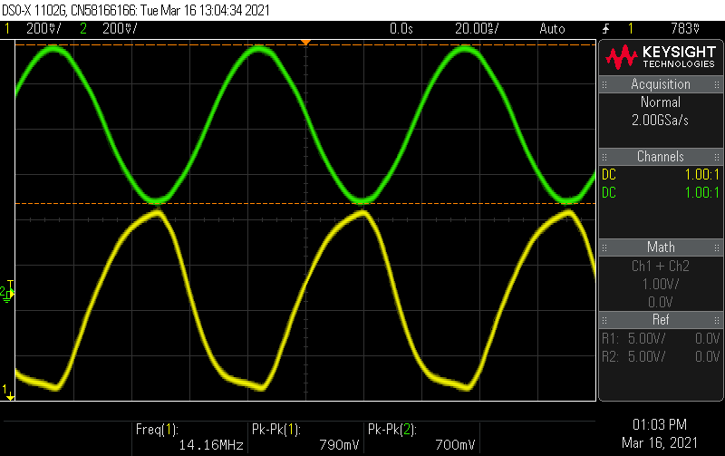
Like any good ham, I tested my tiny transmitter before putting it on the air. The simple dummy load I built back near the beginning of this series came in hand for that, since I was able to hook it up directly to the SMA connector on the breakout board. I connected my oscilloscope to the output and fired up the code. The Si5351 is supposed to generate a square wave; it ended up looking more like a sawtooth wave, but either way, the signal was loaded with harmonics and would need to be cleaned up before going on the air.
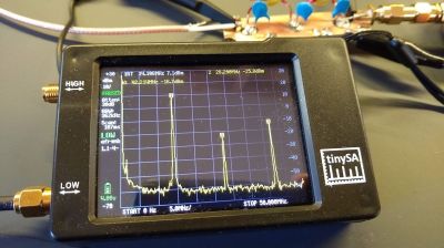
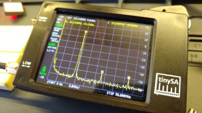
Luckily, low-pass filters that take care of this important bit of spectral hygiene are pretty simple. You can buy them, but this is all about homebrewing, so I spun up a Charlie Morris (ZL2CTM) video on filter design, ran through his math, and came up with values for the capacitors and inductors needed for a filter that cuts off everything above about 14.2 MHz. I used this toroid calculator to figure out how to wind the coils, soldered everything up on a scrap of PCB that had pads cut into it using a cheap plug-cutter bit from Harbor Freight, and tested it using my NanoSA spectrum analyzer.
Having never built a filter like this before, I was surprised how well it did cleaning up the harmonics. The waveform on the scope was a nice, smooth sine wave, and the spectrum analyzer showed a marked decrease in harmonics. The second harmonic, which at 42 MHz is well up into the VHF band, was attenuated by 35 dBm. That’s exactly the kind of spurious a responsible ham wouldn’t want to be spewing around, so I’m glad I built the filter.
On the Air – Sort Of
Once I was confident that my little transmitter was putting out a clean signal, I checked to make sure it was putting out signal that was both on-frequency and properly encoded. The Si5351 dev board isn’t exactly a lab-quality signal source — while it holds the set frequency pretty well, it may or may not output the programmed frequency. So the board needs to be calibrated, which is normally a simple matter of tweaking a correction factor in code while monitoring the output on a frequency counter. Sadly, there’s no “NanoFrequencyCounter” in my tiny test suite — yet — so I had to get creative.
My approach was to tune my HF rig to the desired frequency of the WSPR transmitter — 14.097100 MHz — and slowly adjust the transmitter’s frequency while transmitting into a dummy load. This produces an audible beat frequency which pretty much disappears when the two frequencies match. I wasn’t able to completely eliminate the beat frequency, but I did get it down to a couple of Hertz, which I considered close enough.
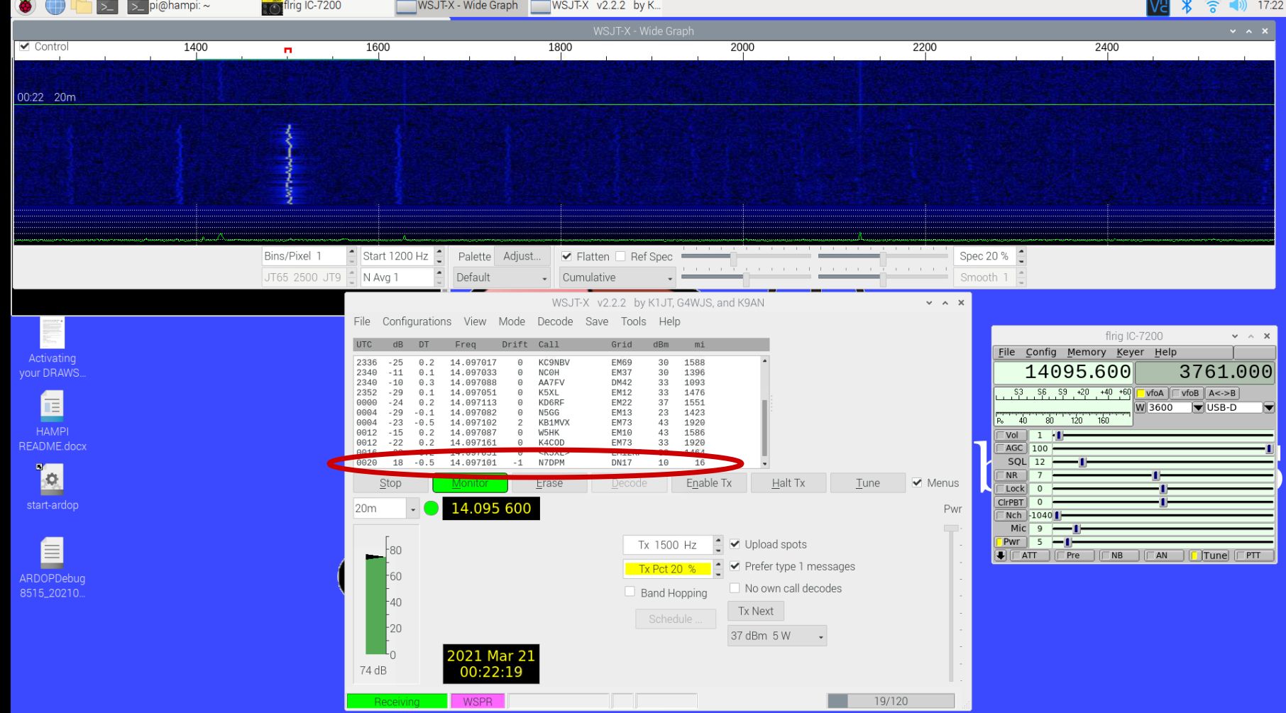
I next checked for a decodable signal by firing up WSJT-X and “broadcasting” to my HF rig. Even with the dummy load connected, I was getting a very strong signal on the waterfall display, and could clearly see the FSK-modulated signal. And I was very pleased to see that WSJT-X cleanly decoded my message.
Better Luck Next Time
Encouraged by these successes, and knowing that plenty of people have made transcontinental WSPR contacts with less power than the 13 mW my little beacon was putting out, I tried getting on the air for real. I hooked the beacon up to my end-fed half-wave antenna and pushed the send button at the appointed time. Sadly, though, I was never able to get any other station to decode my signal. I’ve tried dozens, perhaps hundreds, of times in the last week or so, but I don’t appear to be getting through.
I know my signal is properly encoded, and I know I’m on frequency, so I’m pretty sure the problem is either my antenna or my low-power signal. Given the nature of this series, I’m more inclined to address the latter with a simple power amplifier build. I’ve got a couple of designs in mind for that and I’ve ordered some parts, so we’ll look at that in the next installment and see if I can unlock this particular achievement.


Post a Comment