Decoding the PS/2 Keyboard Protocol Using Good Old Fashioned Hardware

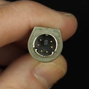
1987 was a glorious year. It brought us the PS/2 keyboard standard that’s still present on many a motherboard back panel to this day. (It also marked the North America/Europe release of The Legend of Zelda but that’s another article.) Up until this point, peripherals were using DIN-5 and DE-9 (often mistakenly called DB9 and common for mice at the time) connectors or — gasp — non-standard proprietary connectors. So what was this new hotness all about? [Ben Eater] walks us through the PS/2 hall of fame by reverse-engineering the protocol.

This is a clocked data protocol, so a waveform is generated on the data pin for each key pressed that can be compared to the clock pin to establish the timing of each pulse. Every key sends a unique set of encoded pulses and voila, the whims of the user can quickly and easily be decoded by the machine.
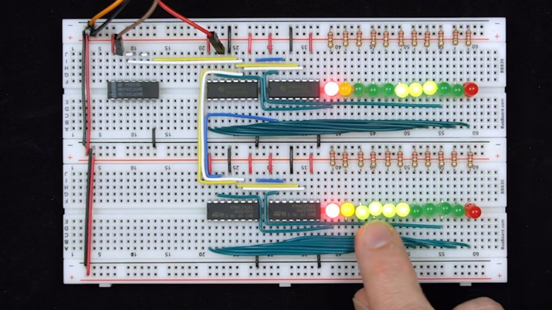
This is where [Ben’s] dive really shines, we know he’s a breadboarding ninja so he reaches for some DIP chips. A shift register is an easy way to build up a parallel PS/2 interface for breaking out each data packet. There are a few quirks along the way, like the need to invert the clock signal so the shift register triggers on the correct edge. He also uses the propagation delay of a couple inverter gates to fire the 595 shift register’s latch pin slightly late, avoiding a race condition. A second 595 stores the output for display by a set of LEDs.
Beyond simply decoding the signal, [Ben] goes into how the packets are formatted. You don’t just get the key code, but you get normal serial interface error detection; start/stop bits and a parity bit as well. He even drills down into extended keys that send more than one packet, and a key-up action packet that’s sent by this particular keyboard.
This is the perfect low-level demo of how the protocol functions. On the practicality side, it feels a bit strange to be breaking out the serial to parallel when it would be very easy to monitor the two signal lines and decode them with a microcontroller. You might want to switch it up a bit, stick with the clock and data pins, but connect them to a Raspberry Pi using just a few passive components.
Post a Comment