
Cable Mechanism Maths: Designing Against the Capstan Equation
I fell in love with cable driven mechanisms a few years ago and put together some of my first mechanical tentacles to celebrate. But only after playing with them did I start to understand the principles that made them work. Today I want to share one of the most important equations to keep in mind when designing any device that involves cables, the capstan equation. Let some caffeine kick in and stick with me over the next few minutes to get a sense of how it works, how it affects the overall friction in your system, and how you can put it to work for you in special cases.
A Quick Refresher: Push-Pull Cable Driven Mechanisms
But first: just what exactly are cable driven mechanisms? It turns out that this term refers to a huge class of mechanisms, so we’ll limit our scope just to push-pull cable actuation systems.
These are devices where cables are used as actuators. By sending these cables through a flexible conduit, they serve a similar function to the tendons in our body that actuate our fingers. When designing these, we generally assume that the cables are both flexible and do not stretch when put in tension.
Since these cables are flexible, they can only exhibit a pull force, not a push, so cables often come in pairs to actuate along both directions. Here, they’ll be opening and closing the jaws of the Chomper.
Here, the joystick controls the yellow jaw of our Chomper by means of two cables, either of which can be put in tension. One of the key elements behind cables is the ability to reroute the direction of the applied force by controlling the cable through thin sheaths or conduits like so:
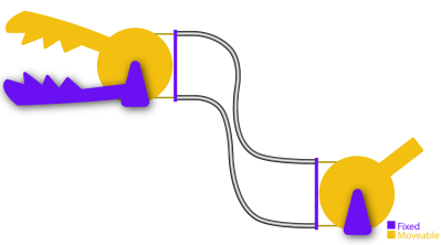
In this setup above, we can still control the Chomper remotely through the joystick and the mechanical control cables, albeit, with some added friction. Ideally, the conduits routing the cable are extremely flexible and do not compress when a compressive force is applied to them. That might sound like sort of magic component–but it’s not! It’s actually just a long skinny extension spring like these parts from DR Templeman. These parts go by a few names: continuous-length extension spring, spring guide… but I’ll generally refer to them as spring guide when referring to them in animatronics projects. This spring guide is extremely flexible, but also resistant to being compressed since it’s made from stainless steel.
If the above example seems a bit far-fetched, take the braking system on your bicycle as an example of a cable-actuated setup. Here, your hand squeezes the brakes on one end of the bike, which moves a length of cable running through a sheath on your bike, which moves your brake calipers and eventually squeezes the rim of your wheel hub to slow you down. Instead of a second conduit, however, an extension spring provides the return force to open the brake calipers when we release the handle.
All in all, these mechanisms really shine in situations requiring tight clearances, backlash-free control, and a limited angle of rotation. Properly designed, cable drives can be made to be both backlash free and back-drivable. But they’re no miracle elixir here. They have limits, and the capstan equation is fundamental to understanding your biggest challenge when it comes to their design: friction.
You vs. Friction: Conduit Edition
Wouldn’t it be neat if we could control anything remotely, using mechanical control cables from a distance? I totally agree! But it’s worth asking, what’s preventing us from weaving our cable and conduit in and out of some arbitrary setup? The answer comes down to friction. Friction is our enemy here, putting a limit to how much we can physically bend the conduit before it becomes too difficult to move. But the specific relationship to our problem is rather unintuitive! To build up a rigorous understanding of how friction affects the cable, let’s start by working a sample problem.
Let’s get rid of the conduit for a minute and start with a crude model using just two ingredients: a cable and a cylinder. In the image below, we’ve wrapped the cable partially around a fixed cylinder, and we’ve put both ends of the cable in tension so that the cable hugs the cylinder. Keep in mind that the cylinder can’t rotate, so if we wanted to move the cable, we’d have to fight friction here and rub up against the cylinder.
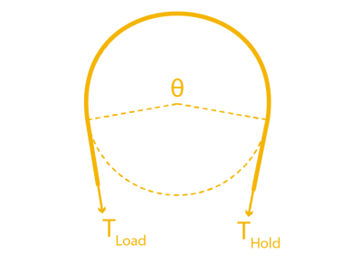 Now let’s start by putting both sides in tension with two tension values: TLoad and THold. We’ll keep the tension constant on THold, but let’s slowly increase value of TLoad. If our cylinder were actually frictionless pulley, trying to create a mismatch in tension would be impossible; the tension on one side would always be equal to the tension on the other side. But because our cylinder is fixed, it is, in fact, possible to increase the tension on one side while keeping the tension on the other side constant, all while the rope doesn’t slip in the process. This happens because static friction on the cylinder is acting against the tension increase up to a certain limit.
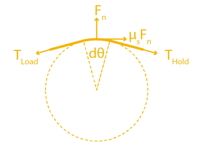
If we zoom in on a cross section of rope to examine the forces acting on a small sliver, we can see how static friction is acting against TLoad, which is equalizing the tension mismatch so that the cable doesn’t slip.
So here’s the big question: for a fixed value of THold on one side of the cylinder, just how much am I allowed to increase the TLoad on the other side before the cable slips and starts rubbing on the cylinder? (Heads-up! The full derivation requires some calculus and differential equation knowledge, but, for the curious, have a look at this PDF.)
TL;DR: the answer is the Capstan Equation. It tells us that, for a given holding tension on one side, the maximum amount of tension we can put on the other side of the cable without slipping is given by:

Moving both T’s over to one side gives us something a little more interesting: a ratio between two tensions.

Let’s have a look at this equation’s inputs. µs is the cable’s coefficient of static friction, a material property that we can look up in a table or material datasheet. θ is the total bend angle between your two tension vectors, TLoad. and THold, measured in radians. TL and TH are the magnitudes of each respective tension value.
Also, an important side note: the bend angle θ is cumulative. In other words, if you add another fixed cylinder into the mix, you have to add up the total bend angle there too. That’s true even if the angle bends in the opposite direction as shown below:
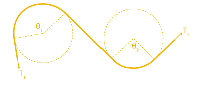
So the total angle that we’d put in the capstan equation is given by θ1+ θ2.
What’s key here is that only two properties, bend angle and coefficient of static friction, will dictate just how much extra tension we can add on one side before the whole setup slips. So what can we glean from this equation?
The first key takeaway is that the cylinder size has no effect on the amount of friction mismatch. In other words, a small radius cylinder will produce the same resulting value that a large radius cylinder would, provided that the overall bend angles are the same. That’s not intuitive! I should mention, though: the equation above assumes that the cable is infinitely flimsy, which is a good approximation unless our bending radius is really small, like a few multiples of the cable diameter. In that case, the force required to bend the cable does matter. But, for most situations, we can ignore it.
Another key takeaway is that the relationship is exponentially related to the bend angle! So while one wrap around the cylinder might not add much friction, adding a second wrap more-than-doubles the maximum tension ratio between the two cable ends. For an example, with a cable who’s µs = 0.3, two wraps is 6.6 times more friction than one wrap. Three wraps is 43.4 times more friction than one wrap [math link]. But if our µs = 0.2, than three wraps is only 12.3 times as much friction as one wrap. In short, exponential relationships are not intuitive and add up quickly, and picking a cable with a coefficient of friction that’s as small as possible (like this nylon-coated cable) is key to keeping the excess friction low.
On its own, this example feels pretty obtuse, so let’s tie it back to our original problem with our cable-driven chomper using conduits. To translate the takeaways from problem to our setup, we simply substitute the cylinders above with conduit, and–voila–the exact same equation applies to this setup also! Since both the cylinder and the conduit are fixed, the capstan equation applies to this situation too. Here the cumulative bend angle is coming from the total bend of the cable that’s in tension.
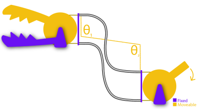
Notice that I only marked angles θ1 and θ2 on one conduit, not both. That’s on purpose. For a for a clockwise torque applied to the joystick, only one cable is being put in tension; the other one goes slack. In other words, only the bends on the cable in tension add to the friction cost. If we applied a torque on the handle in the other direction, the friction costs would come from the bends in the other conduit. In practice, we’d probably route both of these conduits together as a single bundle, but it’s important to realize exactly who’s responsible for the friction depending on the direction of the input.
Designing Around Friction Costs
Applied to our Chomper setup, the Capstan Equation tells us just how much harder we have to tug on one side of the cable before we can get the other side of the cable to start moving. If we know the our cable’s coefficient of static friction and can estimate the max bend angle of our setup, we can estimate the maximum tension value our setup will ever encounter, which, in turn, helps us spec a motor with the appropriate amount of torque.
But there’s another, even simpler takeaway from this equation that we can use as a general rule of thumb. When it comes to designing your own cable driven mechanisms that use conduit, we want to remove any unnecessary bends anywhere else in the cable. In other words, conduits aren’t a catch-all solution for routing a pull force anywhere else in our system. Every bend that we add to them adds a friction cost, and that added friction can be computed with the capstan equation.
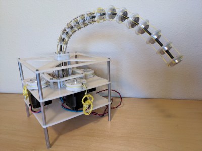
Now that we know how friction and bend angle are related, how could I adjust my design to reduce some of the unnecessary friction that the motors will need to fight through? (I confess that I didn’t know the capstan equation when I made this setup.)
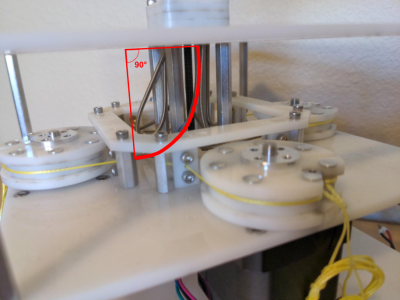
If your system needs to route cable through a host of bends, consider introducing pulleys to do some of these bends for you. Since pulleys roll freely, they don’t add friction, and, therefore, do not contribute to the cumulative bend angle in the capstan equation.
A Teaser: The Inverse Problem
While the Capstan Equation is a huge bummer for preventing us from endlessly weaving our conduit through hard-to-reach sections of our design, a few cases exist where that friction is extremely useful. Since the tension on one side is exponentially related to the tension on the opposite side, with only about four wraps, we can actually use the capstan cylinder to drive the cable directly without worrying about the wire slipping.
This marvelous property gives way to a mechanism called a capstan drive, a cable wrapped around a small shaft that can be used as an actuator. Here, we’ve put the Capstan Equation to work. We’re counting on that exponential relationship so that our cable doesn’t slip while the cylinder is rotated. These mechanisms are just too cool to gloss over, so we’ll revisit them in a future post. Until then, we hope this brief intro helps you think a bit more carefully about routing cables in your next push-pull cable conduit project, tentacles included or not.
References:
- Wikipedia: The Capstan Equation
- Science Direct: The Capstan Equation
- Evaluation and Analysis of Push-Pull Cable Actuation System Used for Powered Orthoses
- CS235: Applied Robot Design, Lecture 7–Introduction to Cable Transmissions
- https://woodenhaptics.org/


Post a Comment